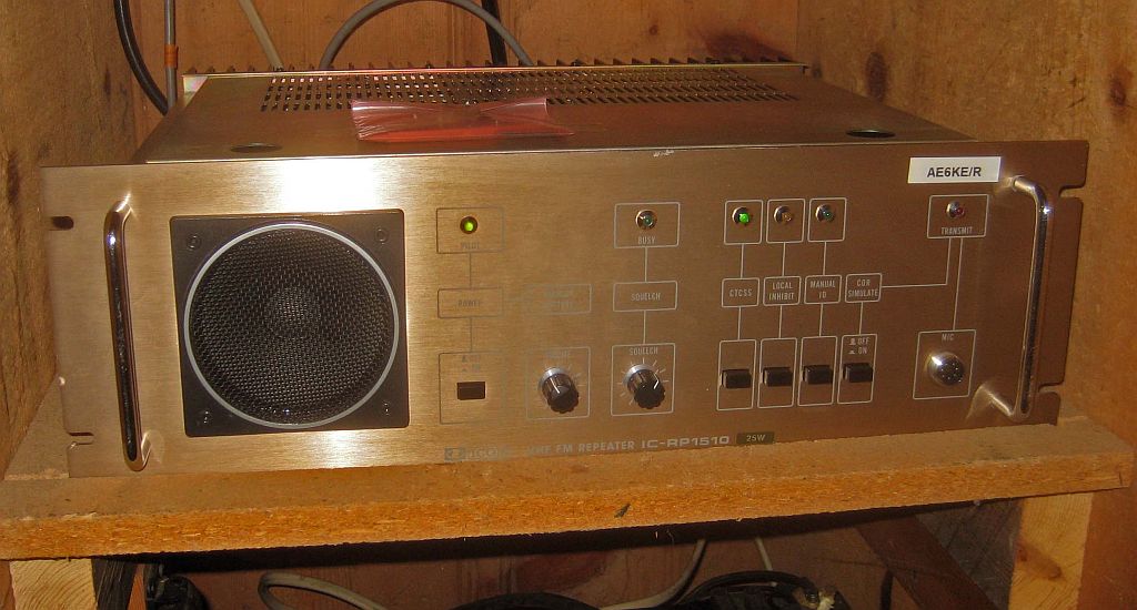
Icom IC-RP1510 146.835+ Mhz 94.8 Hz PL
by Jeff Liebermann AE6KS
2010-02-26
George (AE6KE) reinstalled the repeater.
Icom IC-RP1510 Repeater
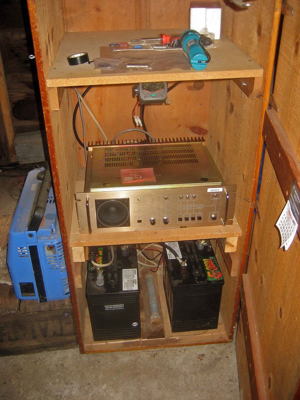
Repeater, batteries, charger, generator, and shelf.
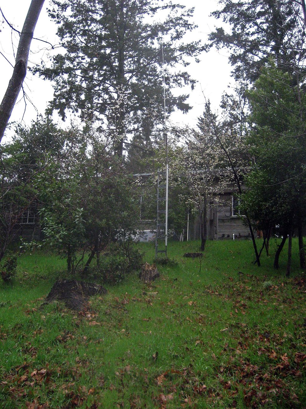
Long antenna, short tower.
2010-02-24
Schematics and documents for the RP-1510. Note that there are apparently two different versions. One version has seperate touch tone decoder and logic boards. This is what's in the printed manual. Another version is a single logic board with the Touch Tone, PL decode, and logic on one board. The only thing I could find is a really awful 2nd generation copy. If anyone has anything better, I would be interested.
2010-02-22
The touch tone decoder is weird. If I punch digits fast enough, ANY digit can be used for the first digit. If I punch digits too slow, it fails to function. I analyzed the schematic and determined that it uses a strobe timer to time the digits. Too slow and it doesn't care what digit comes next. it just drops out. Punch digits fast enough and the 2nd digit rides on the tail of the 1st in the timer window. Great design. However, it sorta works if you punch digits at the right speed. To make it easier, I increased the value of the timing capacitor from 22uf to 47uf.
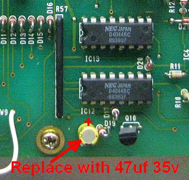
Touch Tone timer tweak.
2010-02-21
How to add a PL encoder to the IC-RP1510 repeater. I used a ComSpec SS-64 PL encoder. Any other PL encoder or decode will also probably work. There is no stock PL input line. Therefore the oscillator can had to be drilled, and an wire inserted through the hole. You'll also need a 10K 1/8w resistor and a small piece of shrink tube. The shrink tube is manditory to prevent accidental shorts inside the oscillator can. Set the tone deviation to +/-750Hz.

Where to inject the PL encode tone.
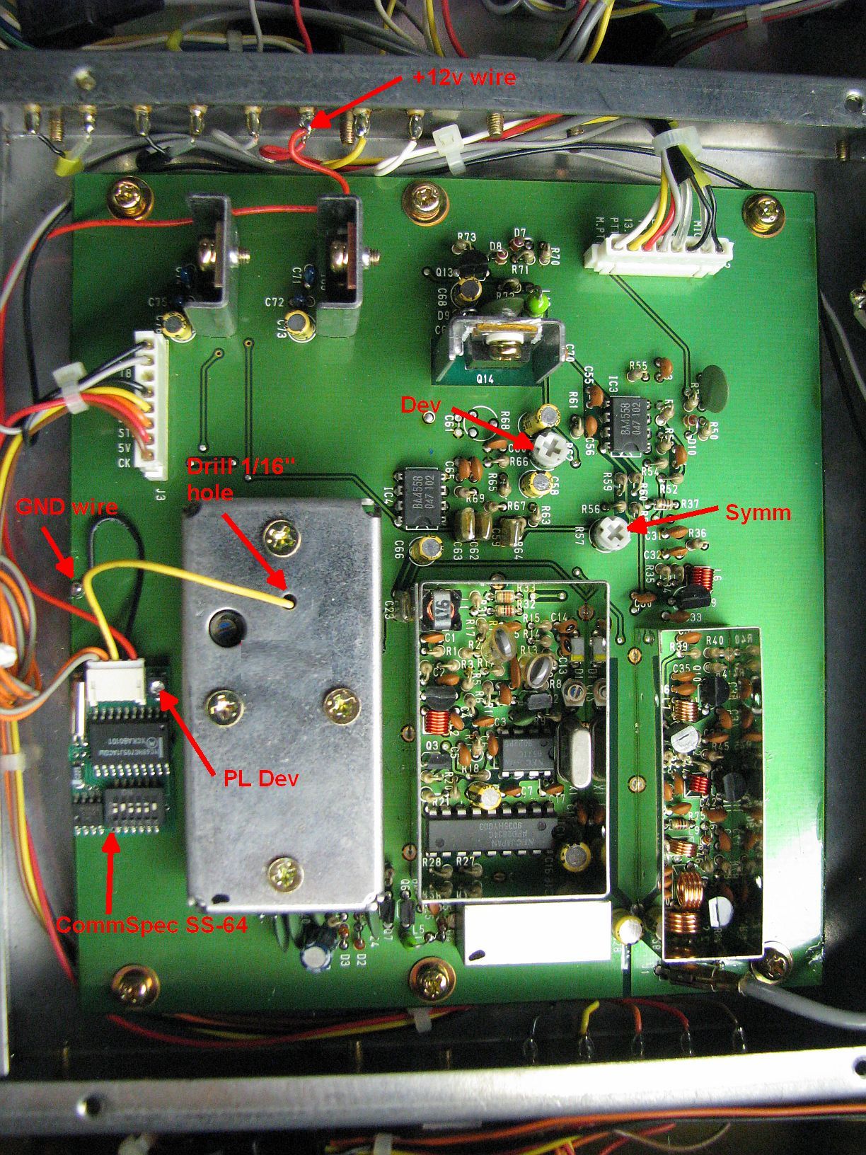
TX assembly when finished.
2010-02-21
Disabled internal battery charger. The problem was that the repeater was running on a battery system that already has a battery charger. Having two chargers on a single battery is a bad idea. Cut the wire shown to disable.
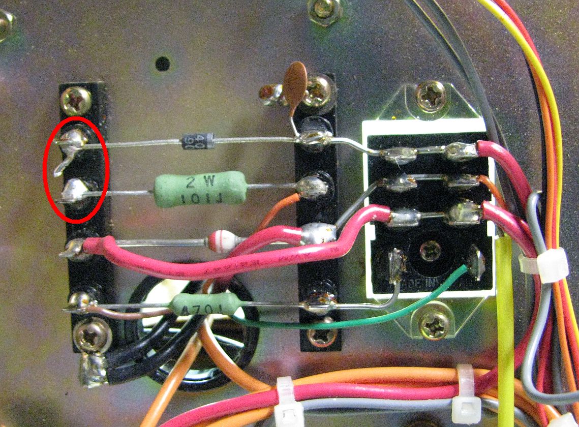
Internal battery charger disable
2010-02-20
The package of paperwork included some xerox copies of what appeared to be just copies of the printed manual pages, but turned out to be a schematic and layout of the real controller card schematic. I would be dead in the water without this. It's somewhat difficult to read as it appears to be a 2nd or 3rd generation copy, but it's better than nothing. Any idea where the original schematic is hiding?
It turns out that the 80C35 CPU is doing very little on the board. Almost everything I'm working on is done with discrete logic, JK flip flops, RC deglitching, and other nightmares I thought I had left behind in the 1970's. As near as I can tell, the 80C35 runs the timers and CW ID. Everything else is discrete logic.
I solved what I consider to be the #1 headache. The box now powers on with the PL enabled. The controlling device was one of the JK flip flops. It gets initialized by an output line from the 80C35 (what a waste of precious i/o). I just moved the init line to the other side of the JK. I think it's now safe to run it on 117VAC only and not worry about the PL turning off with every power glitch.
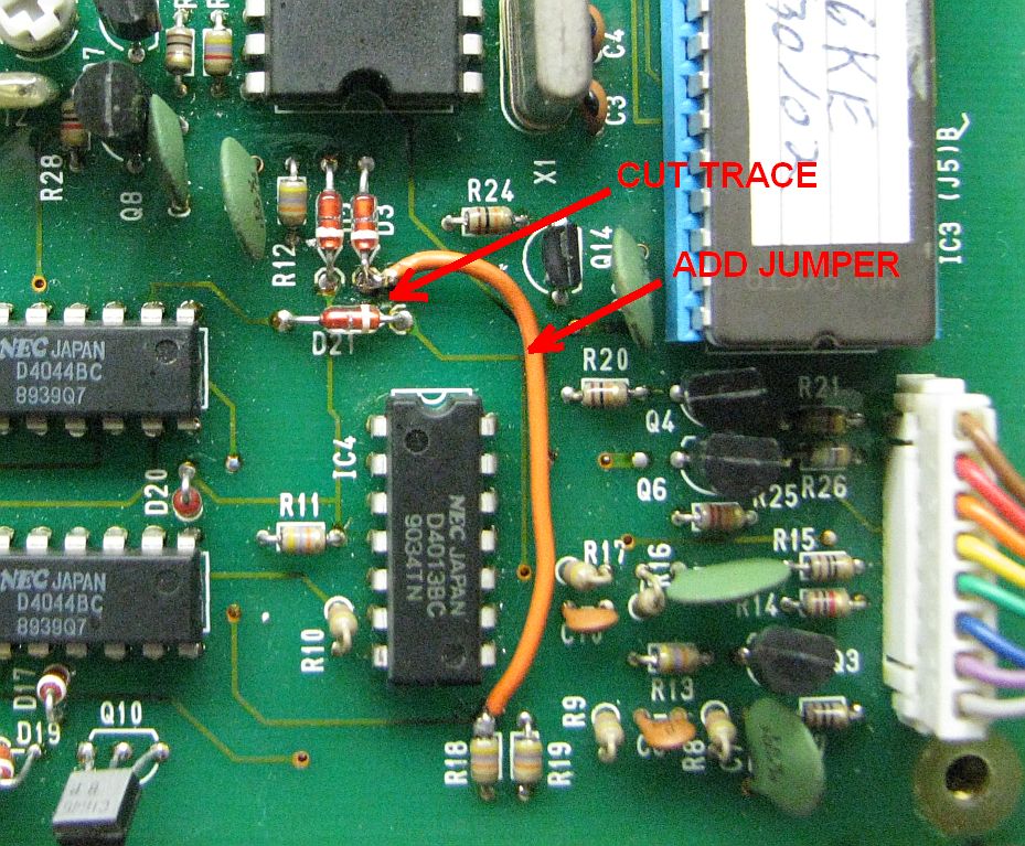
PL decode default on modification.
Neither the above schematics or information can be found anywhere on the web. Believe me, I've tried. I need to carefully document this mess for general consumption.
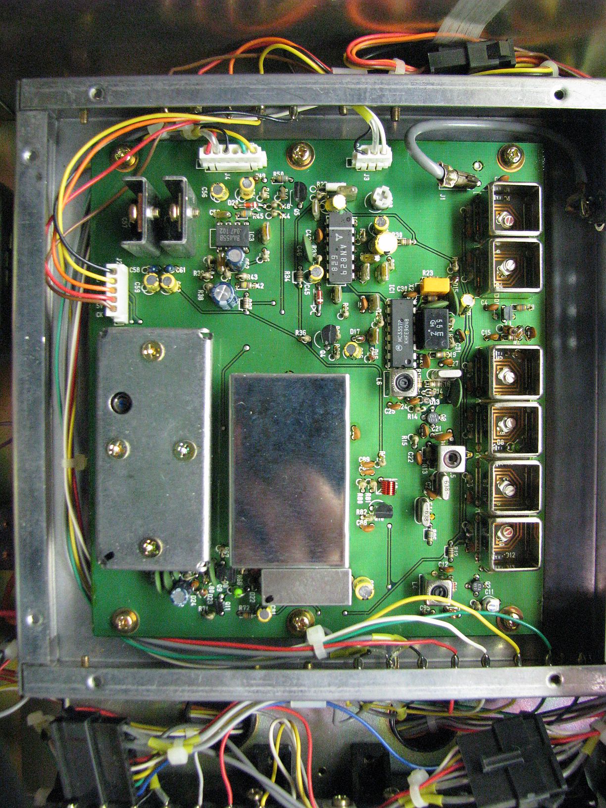
Photos of the controller card and frequency dip switch card BEFORE I started making changes. The jumpers for control codes may change,but I think the dip switches and jumpers will remain the same (not sure).
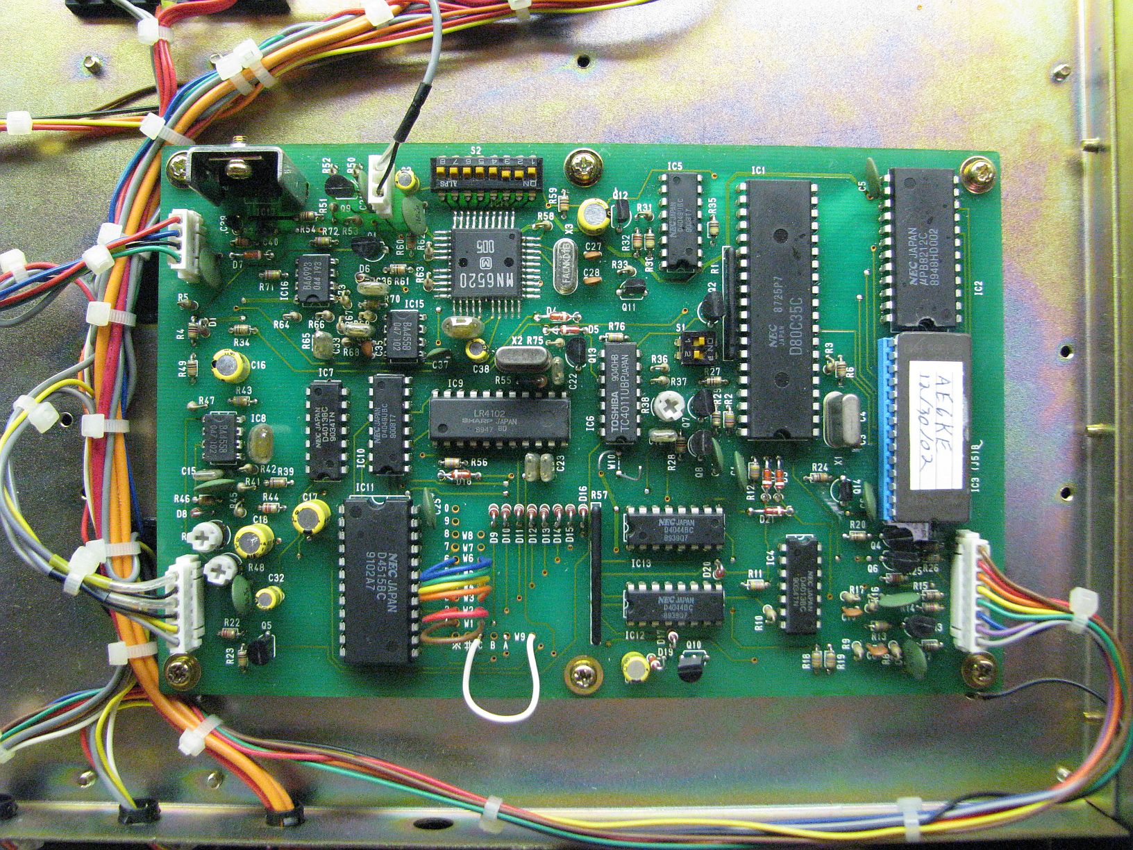
Tone decoder and repeater controller card.
Receiver
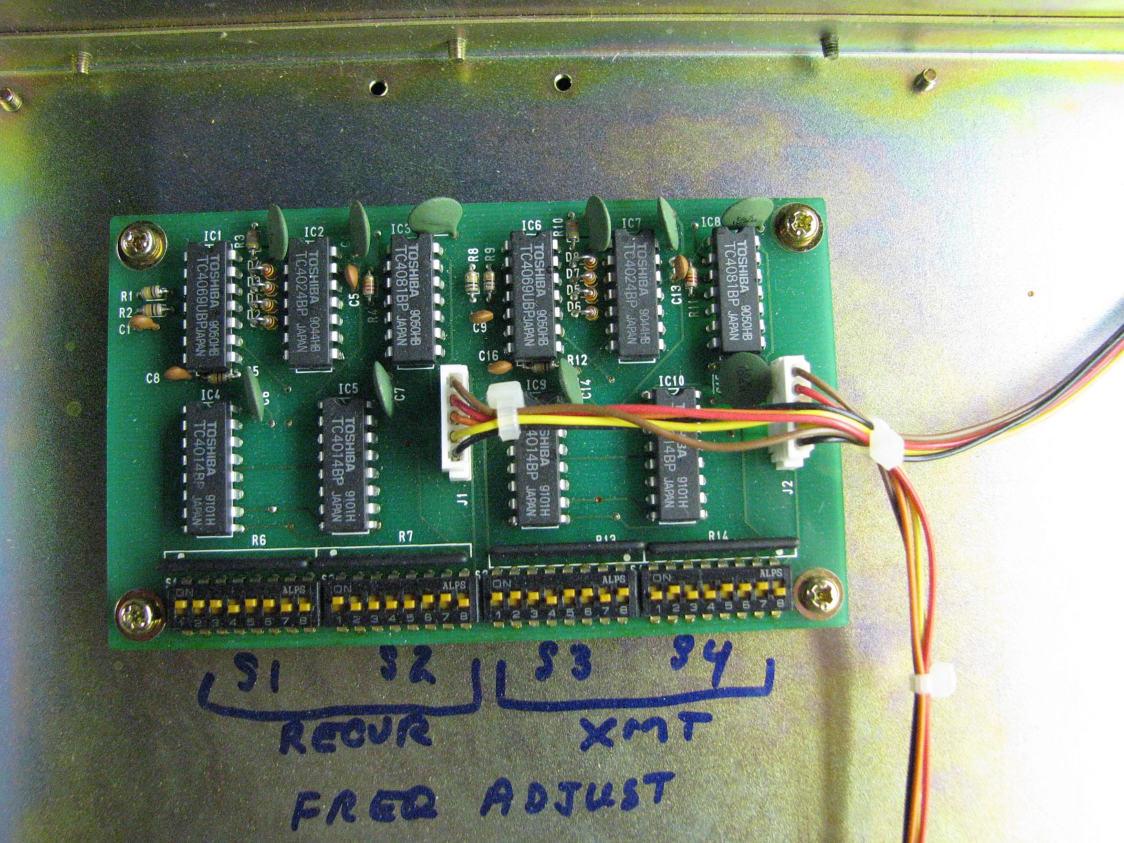
Frequency synthesizer programming. Setting shown are for the AE6KE repeater on 146.835 MHz TX and 146.235 MHz RX.
2010-02-18
Cleaned out dust and spiders. Cleaned crud off front panel. Some screw heads stripped out. 3mm(?) computer screws seem to fit. Aluminum heat sink fin bent back into shape. Front right rack handle bent and loose. Fixed.
The printed manual does NOT resemble the actual repeater. The RF sections appear to be the correct, but the manual shows seperate boards for the touchtone decoder and controller, while actual unit has both conglomerated onto one board. Fortunately, there seems to be a marginally readable copy of the real schematics and board layouts in the documentation pile. There is hope.
Quick bench test. It plays repeater nicely but no touchtone control. Well, not exactly. The PL is programmed for C125(on) and C126(off). Neither works. However B125(on) and D126(off) does work. Now, that's weird. Design error as it seems to be the same on both repeaters (W6JWS/R-2m also).
2010-02-19
Things to do list:
Culprits
by Jeff Liebermann AE6KS http://802.11junk.com
![]()